Guide
Documenting Your Existing HVAC Controls
A field checklist for capturing equipment, wiring, and control details before you plan any thermostat or controls change.
Updated
Good control decisions start with an accurate record of what is already installed. Before comparing thermostats or planning a controls change, document the existing equipment, wiring, and operating behavior so the review is based on evidence rather than assumptions.
1. Record the equipment
Write down the complete model and serial numbers for every controlled unit, including packaged units, air handlers, furnaces, and any dedicated heating or cooling equipment. The nameplate is the authoritative source; a building's age or appearance is not a substitute for the actual model information.
2. Photograph wiring and record every terminal
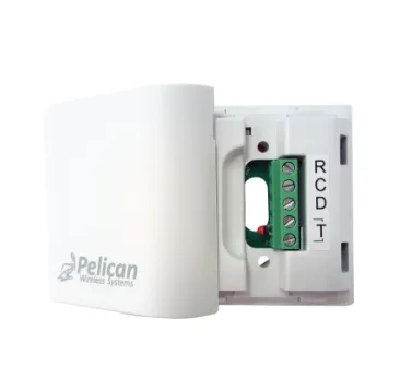
Take clear, well-lit photographs of the existing thermostat or controller, the terminal block, and every labeled wire before anything is disconnected. Then write the connections into a simple table so they can be reconstructed even if a photo is unclear:
| Terminal | Wire color (as found) | Purpose |
|---|---|---|
R / Rc / Rh |
24 VAC power | |
C |
24 VAC common | |
W1 / W2 |
Heat stage 1 / 2 | |
Y1 / Y2 |
Cool / compressor stage 1 / 2 | |
G |
Fan | |
O / B |
Heat-pump reversing valve | |
Other (AUX, E, OCC, S1/S2) |
Accessory / sensor inputs |
Wire color is only a convention, not a standard - always trust the terminal label over the color. Note any jumpers (for example, a factory Rc-Rh jumper) because they reveal whether the equipment uses one transformer or two.
3. Capture control voltage and staging
Measure and record the actual control voltage rather than assuming it. On a multimeter set to AC volts, read between R and C; a commercial low-voltage circuit normally reads ~24-28 VAC (nominal 24 VAC). If you read 120/240 VAC or a millivolt-level signal, stop and flag it - that is a different control class. Then document:
- The number of heating and cooling stages the equipment actually supports.
- Whether control is conventional (heat on
W) or heat pump (reversing valve onO/B, backup heat onW2/AUX). - Fan behavior - whether
Gis energized on a call, continuously, or by schedule. - Any economizer or ventilation interface and which device drives it.
- The transformer VA rating, since connected controls draw continuous current from
C.
4. Note connected devices and network
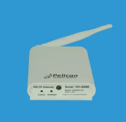
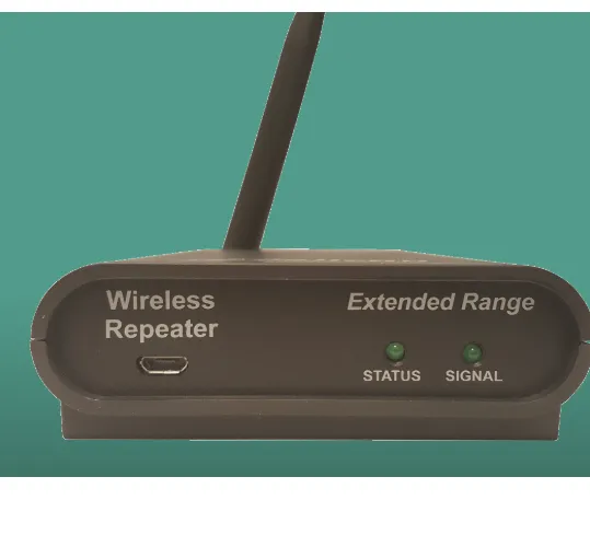
List every connected device: zone panels, equipment controllers, gateways, repeaters, remote sensors, and any building-network components. For each, record model number, location, and what it controls or measures. Note how devices communicate - a wired bus (for example, RS-485 running BACnet MS/TP or Modbus), a proprietary wireless mesh, or a cloud gateway - because a connected control system usually depends on far more than the wall control.
5. Describe the operating goal
Summarize how the space is meant to operate: schedules, occupancy needs, setbacks, remote access, alarms, and any coordination between zones. Separate required behavior from optional conveniences so the priorities are clear.
Keep this record with your project notes. Guidance on this site helps organize a selection review; it is not a compatibility determination, engineering approval, or a substitute for work by qualified personnel. Send project details to sales@coldaircentral.com for help with the review process.