Application
Fan Coil Controls
Review Pelican control options for documented two-pipe and four-pipe fan coil configurations.
Fan coil selection starts with the water circuit and the valve and fan controls. Two-pipe and four-pipe arrangements need different sequences, and similar-looking room thermostats can have very different outputs.
Product option
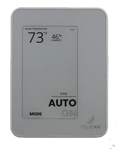
The Pelican TC1 installation guide documents two-pipe and four-pipe fan coil configurations using supported 24 V AC control arrangements. Its diagrams distinguish spring-return and floating water valves and show separate arrangements for two-speed fans.
Use the diagram for the actual valve and fan combination. Pelican calls for technical-support assistance with two-pipe thermostat configuration and the floating-valve configurations identified in its guide.
Before selecting
- Identify whether the equipment uses two or four pipes and how a two-pipe system changes between heating and cooling.
- Record each valve actuator's voltage and operating method.
- Confirm the fan speeds and the interface used to switch them.
- Document any auxiliary heat and the controller outputs it needs.
- Include Pelican gateway and network requirements in the system review.
The listed thermostat is not a universal replacement for line-voltage fan coil controls or every modulating valve. Have the equipment sequence matched to the exact manufacturer diagram before choosing components.
For central equipment serving multiple ducted zones, see Commercial HVAC Zoning.